Long-Range Shooting
This guide covers long-range shooting by accounting for bullet drop and windage.
Requirements
Section titled “Requirements”The following mods are required for this guide, but can be exchanged with mods providing equivalent features:
- RHS Status Quo for Vector 21 range finder
- ACE Scopes for advanced zeroing
- ACE Ballistics for ballistic tables
- ACE Weather for Kacetrel 4500 pocket weather meter
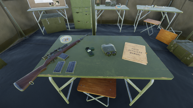
M21, Kacetrel 4500, Vector 21 and ballistic table from left to right.
Workflow
Section titled “Workflow”Our goal is to target the gunner of a stationary armed UAZ. We will first measure the distance and bearing of the target, then measure the crosswind and finally derive the corresponding bullet drop and windage.
Acquiring the Target
Section titled “Acquiring the Target”- Look through the Vector 21 and aim at the target.
- Hold R+V for 2 seconds to get the bearing and distance.
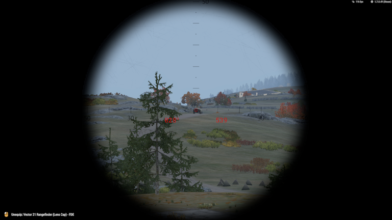
In our case, the Vector 21 reports a bearing of 028° and distance of 539 m.
Measure Crosswind Speed
Section titled “Measure Crosswind Speed”- Put the Kacetrel 4500 in hand and hold R to inspect it. A mouse cursor will appear.
- Switch to the
Directiondata screen (Click with the mouse on the ↑ or ↓ button to switch between the different data screens). - We have to make sure that the correct direction mode is selected:
Magnetic NorthvsTrue N X.X W/E(i.e. true north), which is shown at the bottom of the screen. The two modes are identical, unless you are running ACE Compass with magnetic declination enabled. Vanilla compasses report magnetic direction. In contrast, RHS Status Quo’s Vector 21 reports true direction, unlike its real life counterpart, so we have to switch toTruemode.
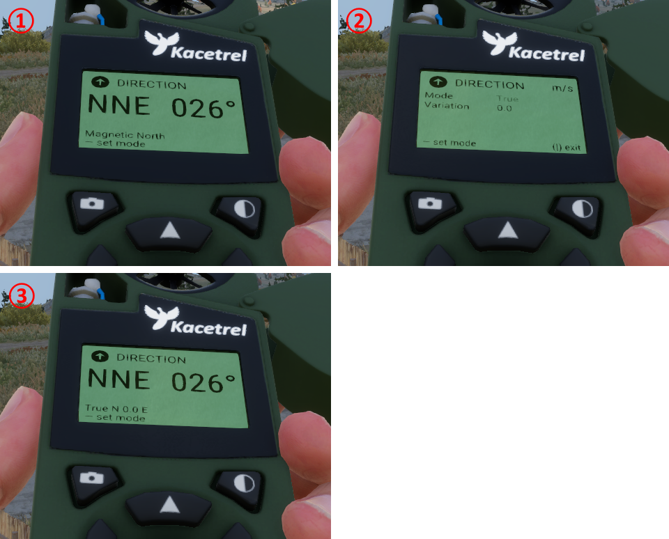
① Magnetic direction data screen. You can modify the direction mode by clicking on the — button.
② Direction mode selection screen. Click the ← or → button to switch from Magnetic to True mode. The Variation corresponds to the declination and is already correctly configured out of the box, so no further changes are needed. Click the — button to confirm the selection. You will be back in the direction data screen, but in the True N X.X W/E mode ③.
③ True direction data screen.
- Switch to the
Crosswinddata screen (Click the ↑ or ↓ button to switch between the different data screens). - Set the reference direction to the direction of the target (i.e. the 028° we measured before).
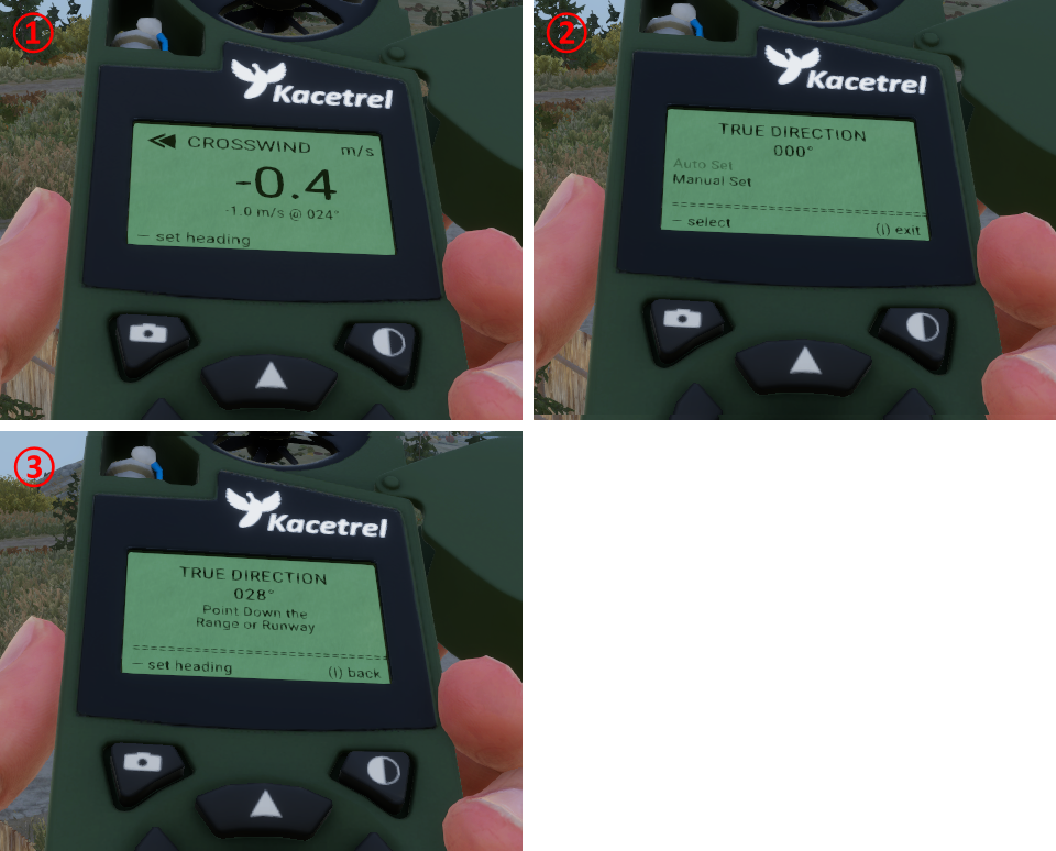
① Crosswind data screen. You can modify the reference direction by clicking on the — button.
② Reference direction screen. Click again the — button to enter Auto Set.
③ Auto set screen. Hold R to exit inspection and turn until the reference direction matches the target (i.e. 028° in our case). Hold R to enter inspection mode and click the — button to confirm the reference. You will be back at the crosswind data screen ①.
- Hold R to exit inspection. Press Shift+K to open the wind info display (you will see a wind barb at the bottom right of the screen).
- Turn until the wind barb points up on your screen. The reported speed value on the Kacetrel corresponds to the crosswind speed, which is 4.5 m/s in our case. A positive speed means that the crosswind component comes from the right of our target, while a negative means left. The sign will be relevant later for setting the
WINDzeroing.
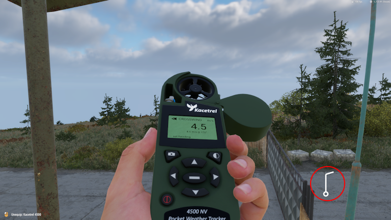
Kacetrel aligned with wind barb for reading the correct crosswind speed.
Derive Zeroings
Section titled “Derive Zeroings”- Put the ballistic table in hand and hold R to inspect it.
- Switch the pages until you get the correct bullet type. In our case we have the M21 loaded with M118 special ball cartridges, so we switch to
Ammo_752x51_Ball_M118. If not sure about the type, open the inventory and hover with the mouse over the magazine to see the description in the tooltip.
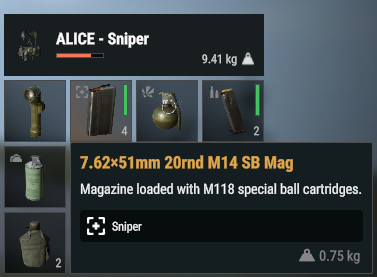
Tooltip confirms that we have M118 rounds.
- Read the drop and wind from the table. In our case we get a drop of -3.2 mrad and wind of 1.8 mrad from interpolation (see details below).
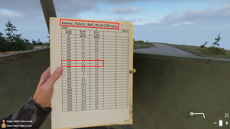
Ballistic data page for M118 rounds. Our measured distance from earlier is 539 m, which lies between 500 m and 550 m. If it has to go fast, take the closer distance (550 m in this case), but you will lose precision. We will instead demonstrate how to get more accurate values from interpolation.
| Range [m] | Drop [mrad] | Wind 4 m/s [mrad] |
|---|---|---|
| 500 | -2.7 | 1.5 |
| 539 | -?.? | ?.? |
| 550 | -3.4 | 1.6 |
We first calculate the differences (Δ) of the entries relative to 500 m:
| ΔRange [m] | ΔDrop [mrad] | ΔWind 4 m/s [mrad] |
|---|---|---|
| 0 | 0.0 | 0.0 |
| 539 - 500 = 39 | --- | --- |
| 550 - 500 = 50 | -3.4 - (-2.7) = -0.7 | 1.6 - 1.5 = 0.1 |
We can then calculate the interpolation scale by dividing the 39 m by 50 m, which yields 0.78. We can finally get the data for 539 m by multiplying the 50 m difference data with the interpolation scale and add the 500 m data to it:
| Range [m] | Drop [mrad] | Wind 4 m/s [mrad] |
|---|---|---|
| 539 | 0.78 * (-0.7) + (-2.7) ≈ -3.2 | 0.78 * 0.1 + 1.5 ≈ 1.6 |
We obtain -3.2 mrad as the final value for the drop. The value for 4 m/s wind is 1.6, but we measured 4.5 m/s. We can obtain the correct value by multiplying the value with our actual speed and divide it by 4 m/s , which is (1.6 mrad) * (4.5 m/s) / (4 m/s) = 1.8 mrad.
Set Zeroings
Section titled “Set Zeroings”- Adjust the DROP and WIND zeroings with advanced zeroing keybinds. For our case
ELEV=3.2(elevation has the opposite sign of drop) andWIND=1.8R(Rfor positive crosswind speed, i.e. crosswind component comes from the right). - Aim at the target and take the shot.
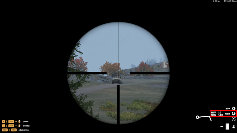
Aiming at the target with the correct zeroings.
Additional Corrections
Section titled “Additional Corrections”Firing at Moving Target
Section titled “Firing at Moving Target”If a target moves, you will have to lead the target (i.e. fire ahead). Some ballistic tables have an additional column called LEAD 1 m/s, which states how many mrads you have to lead a target that moves at 1 m/s for a given distance. For instance, if the target moves at 14 m/s and the correction in the table reports 0.3 mrad, you have to lead the target by (0.3 mrad) * 14 = 4.2 mrad. This value can then be added or subtracted from the wind correction depending on the direction of travel.
Firing Uphill/Downhill
Section titled “Firing Uphill/Downhill”Ballistic tables are calibrated for horizontal shooting. Firing uphill or downhill with these elevation corrections will overshoot the target if the slant angle (i.e. angle between horizontal plane and line of sight) is large enough (roughly 7°, respective -7°). The slant angle can be obtained with the Vector 21 by tapping V once and then pressing and holding V for 2 seconds. The simplest way to compensate for the overshooting is to apply the Rifleman’s rule, which states that you should use the horizontal distance to the target instead of the slant distance (i.e. line of sight distance) for looking up the drop. Given a slant distance and slant angle , the horizontal distance is . Note that the rule only applies to drops. You should always look up the wind correction based on the slant distance regardless of the slant angle. For instance, if the Vector 21 reports a slant distance of 539 m and a slant angle of -13°, then the horizontal distance is (539 m) * cos(-13°) ≈ 525 m. You should therefore look up the drop for 525 m and the wind for 539 m.